Electric Motorcycle Controller
1. What is controller?
● The electric vehicle controller is a core control device used to control the start, operation, advance and retreat, speed, stop of the electric vehicle motor and other electronic devices of the electric vehicle. It is like the brain of the electric vehicle and is an important component of the electric vehicle. Simply put, it drives the motor and changes the motor drive current under the control of the handlebar to achieve the speed of the vehicle.
● Electric vehicles mainly include electric bicycles, electric two-wheeled motorcycles, electric three-wheeled vehicles, electric three-wheeled motorcycles, electric four-wheeled vehicles, battery vehicles, etc. Electric vehicle controllers also have different performances and characteristics due to different models.
● Electric vehicle controllers are divided into: brushed controllers (rarely used) and brushless controllers (commonly used).
● The mainstream brushless controllers are further divided into: square wave controllers, sine wave controllers, and vector controllers.
Sine wave controller, square wave controller, vector controller, all refer to the linearity of current.
● According to the communication, it is divided into intelligent control (adjustable, usually adjusted through Bluetooth) and conventional control (not adjustable, factory set, unless it is a box for brush controller)
● The difference between brushed motor and brushless motor: Brushed motor is what we usually call DC motor, and its rotor is equipped with carbon brushes with brushes as the medium. These carbon brushes are used to give the rotor current, thereby stimulating the magnetic force of the rotor and driving the motor to rotate. In contrast, brushless motors do not need to use carbon brushes, and use permanent magnets (or electromagnets) on the rotor to provide magnetic force. The external controller controls the operation of the motor through electronic components.
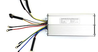
Square wave controller
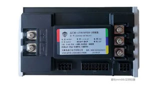
Sine wave controller
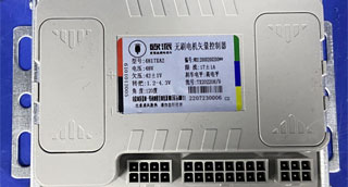
Vector Controller
2. The Difference Between Controllers
| Project | Square wave controller | Sine wave controller | Vector controller |
| Price | Cheap | Medium | Relatively expensive |
| Control | Simple, rough | Fine, linear | Accurate, linear |
| Noise | Some noise | Low | Low |
| Performance and efficiency, torque | Low, slightly worse, large torque fluctuation, motor efficiency cannot reach the maximum value | High, small torque fluctuation, motor efficiency cannot reach the maximum value | High, small torque fluctuation, high-speed dynamic response, motor efficiency cannot reach the maximum value |
| Application | Used in situations where the motor rotation performance is not high | Wide range | Wide range |
For high-precision control and response speed, you can choose a vector controller. For low cost and simple use, you can choose a sine wave controller.
But there is no regulation on which is better, square wave controller, sine wave controller or vector controller. It mainly depends on the actual needs of the customer or the customer.
● Controller specifications: model, voltage, undervoltage, throttle, angle, current limiting, brake level, etc.
● Model: named by the manufacturer, usually named after the specifications of the controller.
● Voltage: The voltage value of the controller, in V, usually single voltage, that is, the same as the voltage of the whole vehicle, and also dual voltage, that is, 48v-60v, 60v-72v.
● Undervoltage: also refers to the low voltage protection value, that is, after undervoltage, the controller will enter undervoltage protection. In order to protect the battery from over-discharge, the car will be powered off.
● Throttle voltage: The main function of the throttle line is to communicate with the handle. Through the signal input of the throttle line, the electric vehicle controller can know the information of the electric vehicle acceleration or braking, so as to control the speed and driving direction of the electric vehicle; usually between 1.1V-5V.
● Working angle: generally 60° and 120°, the rotation angle is consistent with the motor.
● Current limiting: refers to the maximum current allowed to pass. The larger the current, the faster the speed. After exceeding the current limit value, the car will be powered off.
● Function: The corresponding function will be written.
3. Protocol
Controller communication protocol is a protocol used to realize data exchange between controllers or between controllers and PC. Its purpose is to realize information sharing and interoperability in different controller systems. Common controller communication protocols include Modbus, CAN, Profibus, Ethernet, DeviceNet, HART, AS-i, etc. Each controller communication protocol has its own specific communication mode and communication interface.
The communication modes of the controller communication protocol can be divided into two types: point-to-point communication and bus communication.
● Point-to-point communication refers to the direct communication connection between two nodes. Each node has a unique address, such as RS232 (old), RS422 (old), RS485 (common) one-line communication, etc.
● Bus communication refers to multiple nodes communicating through the same bus. Each node can publish or receive data to the bus, such as CAN, Ethernet, Profibus, DeviceNet, etc.
Currently, the most commonly used and simple one is the One-line protocol, followed by the 485 protocol, and the Can protocol is rarely used (matching difficulty and more accessories need to be replaced (usually used in cars)). The most important and simple function is to feed back the relevant information of the battery to the instrument for display, and you can also view the relevant information of the battery and the vehicle by establishing an APP; since the lead-acid battery does not have a protection board, only lithium batteries (with the same protocol) can be used in combination.
If you want to match the communication protocol, the customer needs to provide the protocol specification, battery specification, battery entity, etc. if you want to match other central control devices, you also need to provide specifications and entities.
Instrument-Controller-Battery
● Realize linkage control
Communication on the controller can realize linkage control between different devices.
For example, when a device on the production line is abnormal, the information can be transmitted to the controller through the communication system, and the controller will issue instructions to other devices through the communication system to let them automatically adjust their working status, so that the entire production process can remain in normal operation.
● Realize data sharing
Communication on the controller can realize data sharing between different devices.
For example, various data generated during the production process, such as temperature, humidity, pressure, current, voltage, etc., can be collected and transmitted through the communication system on the controller for data analysis and real-time monitoring.
● Improve the intelligence of equipment
Communication on the controller can improve the intelligence of equipment.
For example, in the logistics system, the communication system can realize the autonomous operation of unmanned vehicles and improve the efficiency and accuracy of logistics distribution.
● Improve production efficiency and quality
Communication on the controller can improve production efficiency and quality.
For example, the communication system can collect and transmit data throughout the production process, realize real-time monitoring and feedback, and make timely adjustments and optimizations, thereby improving production efficiency and quality.
4. Example
● It is often expressed by volts, tubes, and current limiting. For example: 72v12 tubes 30A. It is also expressed by rated power in W.
● 72V, that is, 72v voltage, which is consistent with the voltage of the whole vehicle.
● 12 tubes, which means there are 12 MOS tubes (electronic components) inside. The more tubes, the greater the power.
● 30A, which means current limiting 30A.
● W power: 350W/500W/800W/1000W/1500W, etc.
● Common ones are 6 tubes, 9 tubes, 12 tubes, 15 tubes, 18 tubes, etc. The more MOS tubes, the greater the output. The greater the power, the greater the power, but the faster the power consumption
● 6 tubes, generally limited to 16A~19A, power 250W~400W
● Large 6 tubes, generally limited to 22A~23A, power 450W
● 9 tubes, generally limited to 23A~28A, power 450W~500W
● 12 tubes, generally limited to 30A~35A, power 500W~650W~800W~1000W
● 15 tubes, 18 tubes generally limited to 35A-40A-45A, power 800W~1000W~1500W
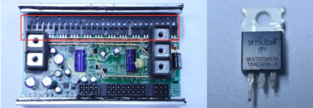
MOS tube

There are three regular plugs on the back of the controller, one 8P, one 6P, and one 16P. The plugs correspond to each other, and each 1P has its own function (unless it does not have one). The remaining positive and negative poles and the three-phase wires of the motor (the colors correspond to each other)
5. Factors Affecting Controller Performance
There are four types of factors that affect controller performance:
5.1 The controller power tube is damaged. Generally, there are several possibilities:
● Caused by motor damage or motor overload.
● Caused by poor quality of the power tube itself or insufficient selection grade.
● Caused by loose installation or vibration.
● Caused by damage to the power tube drive circuit or unreasonable parameter design.
The drive circuit design should be improved and matching power devices should be selected.
5.2 The internal power supply circuit of the controller is damaged. Generally, there are several possibilities:
● The controller's internal circuit is short-circuited.
● The peripheral control components are short-circuited.
● The external leads are short-circuited.
In this case, the layout of the power supply circuit should be improved, and a separate power supply circuit should be designed to separate the high current working area. Each lead wire should be short-circuit protected and wiring instructions should be attached.
5.3 The controller works intermittently. There are generally the following possibilities:
● The device parameters drift in high or low temperature environments.
● The overall design power consumption of the controller is large, which causes the local temperature of some devices to be too high and the device itself enters the protection state.
● Poor contact.
When this phenomenon occurs, components with suitable temperature resistance should be selected to reduce the overall power consumption of the controller and control the temperature rise.
5.4 The controller connection line is aged and worn, and the connector is in poor contact or falls off, causing the control signal to be lost. Generally, there are the following possibilities:
● The wire selection is unreasonable.
● The protection of the wire is not perfect.
● The selection of connectors is not good, and the crimping of the wire harness and the connector is not firm. The connection between the wire harness and the connector, and between the connectors should be reliable, and should be resistant to high temperature, waterproof, shock, oxidation, and wear.

